80 m loading coil for the JPC-12 antenna

fig 1. My JPC-12 with the DIY 80 meter band loading coil added

I use the JPC-12 antenna as a portable antenna. The JPC-12 is essentially a center loaded vertical antenna, that can be used from (slash designed for) the 20 to 40 meter bands (or higher bands, see below). The band of choice is selected by adjusting the inductance of the loading coil. This loading coil can be adjusted by moving a slider, tapping the right inductance for a particular band/frequency.

Higher bands (above 20 meter)

By the way: by leaving the coil out, the antenna is also suitable for the higher bands. Adjustment is then done by adjusting the length of the telescopic whip. In this blog I will not focus on the higher bands though, my focus is on adding an extra band: the 80 meter band.

Adding the 80 meter band to the JPC-12 antenna

So I want to use the JPC-12 also on the 80 meter band. How to do this? By enlarging the inductance of the loading coil arrangement. And by adding an extra (and longer) counterpoise wire.

This is how I did it:

The design I had in mind was to use both an extra loading coil Γ‘nd the original JPC-12 loading coil together (so in series). The basic idea behind this idea is that the extra loading coil (and extra counterpoise) should bring resonance for the 80 meter band itself. And the JPC-12 loading coil then should be able to tune the antenna within the 80 meter band.

The necessity for in band tuning is because the JPC-12 vertical element is only 4,1 meter (about 13.5 ft) ‘tall’ and therefore has a very narrow bandwidth when tuned to 80 meter. Due to this narrow bandwidth only a portion of the 80 band can be used without retuning.

Now 4,1 meter is adequate for the 20 meter band. And it is OK-ish for 30 meter band. For the 40 meter band it is definitely a compromise. For the 80 meter band a 4,1 meter vertical is … well.. extremely short. A quarter wave length on 80 meter is 20 meter, so the JPC on 80 meter has only one fifth of the desired optimal length! But it’s 4,1 meter is better than nothing!

So, as a consequence of the shortness on 80 meter a very narrow bandwidth should be expected. Way less than the total bandwidth of the 80 meter band. To be able to use this antenna in any meaningfull way some kind of in band tuning is necessary. There the original JPC-12 loading coil comes in, as it can be adjusted to fine tune in band. So far my tinkering. Next question: is this feasable?

I took my VNA, my soldering iron, winding wire and started winding the extra loading coil. I also made an extra counterpoise and added to the other counterpoises.

After experimenting with different setups I found this setupworks works perfectly:

  • first: add an extra counterpoise wire with a length of 20 meter;
  • then: add the DIY coil and give it just enough inductance to get the JPC-12 on the lowest part of the 80 meter band. This with the JPC-coil in the position that gives the highest inductance.
  • the best place for the 80m coil is between the lower sections (the black rods) and the original tuning coil of the JPC-12;
  • now you can tune the JPC-12 anywhere on the 80 meter band, just by adjusting the original JPC-12 loading coil!

This is how I made the 80 meter loading coil:

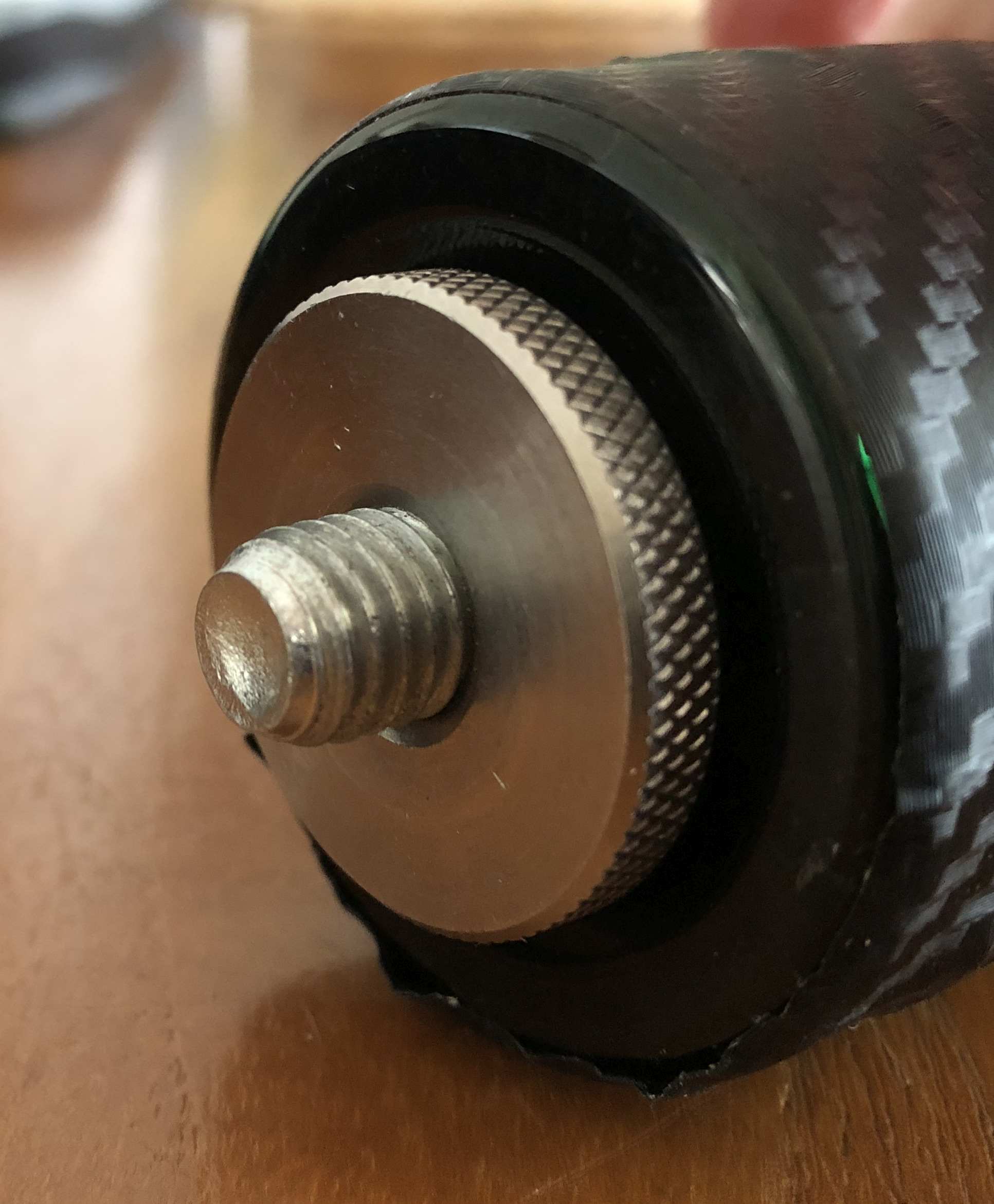
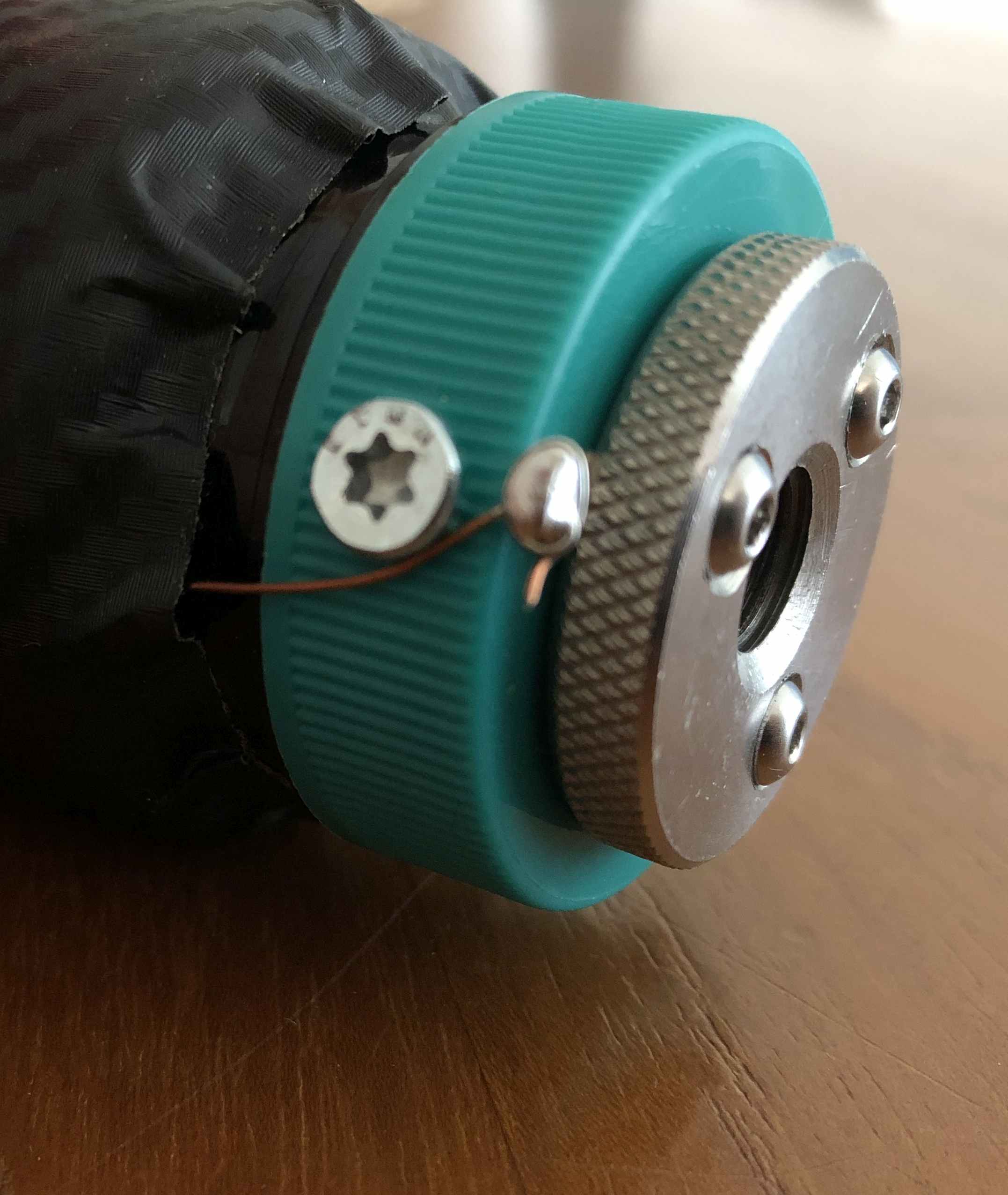
Mechanicaly: The JPC-12 uses M10 fittings to connect the different parts together. Male and female. I needed something like that to connect my DIY 80 meter loading coil into the antenna (between the black rods and the JPC inductor). As a form for the windings and the M10 fittings I used a discarded plastic vitamine container. To make the connecting parts I used two big M10 (10 mm inner diameter) and 4 cm outer diameter thumb-screws. And a M10 bolt to create the male part. The first thumb screw (the ‘female’) was placed at the lid, secured with three M3 screws and with a soldering eye fitted for the electrical connection. At the bottom of the container I created a ‘male fitting’ by drilling a 10mm whole in the bottom of the plastic container, put the M10 bolt through the hole from the inside out and fixed this bolt by screwing the thumbscrew on from the outside. A bare wire was clamped inbetween. Now I was able be to fit my ‘vitamin container loading coil’ between the black rod and the original JPC-12 loading coil. Ready for measuring…

For the loading coil itself: I wound it on the outside of the vitamin container and electrically connected it to the ends of the top and bottom fittings. See the picture to get an idea how this looks like. I picture tells more than words πŸ˜‰

The 80 meter coil itself has the following dimensions:

The container is 45 mm (1.77 inch) in diameter, with 33 windings close together. I used 0,6 mm (19 AWG) enamelled copper wire. With this coil (together the original JPC-tuning coil for in band tuning) I can adjust for any frequency within the entire (regio 1) 80 meter band!

After measuring -and double checking- I protected the coil I by covering it with black plastic wrap foil. The picture below is of the container still without the foil: you can see the bare loading coil.

fig 2. the 80 meter loading coil without plastic wrap

Some further thoughts on the design

As you can see, the plastic container I used is a bit big for the coil. Also this container is not the most sturdy thing. So a more compact and sturdier design is certainly possible!

Also: I used 0,6 mm enamel wire. Thicker wire, say 1 mm, will be better (higher Q, lower losses and able to withstand more power). But 0,6 mm is what I had lying around (like the vitamin container .. ) and I will only be using QRP power anyway. So for now this is good enough for me. I plan on a better ‘MKII ‘version, though πŸ˜‰

A last remark on the enamel wire. Beware that heavier wire (and the same 33 windings) also means that the coil width is changed, and hence the inductance will be different! Keep this in mind (use a VNA to check the result)!

Now back to the results of my little project:

I’m happy for now: in the figure below you can see the measurements I made with my vector analyzer. Nota Bene: the grey area represents the entire regio 1 80 meter band.

The red curve corresponds with the slider of the JPC-12 loading coil in the lowest position (i.e. exactly at the low red mark on the JPC loading coil). The blue curve with the slider of the loading coil in the highest position (i.e. exactly at the high red mark on the JPC loading coil)!

I.M.H.O. this is perfect!
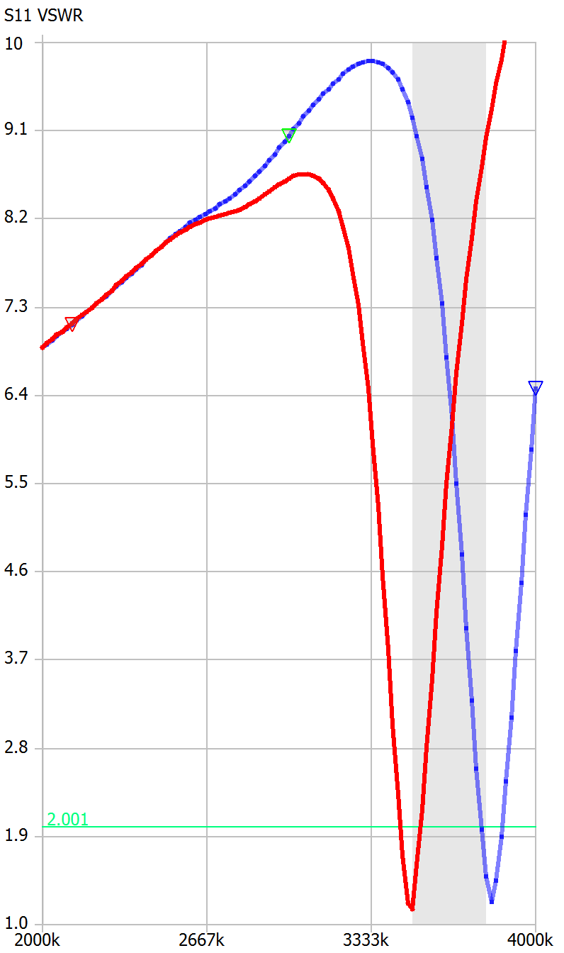
fig 3: VSWR and tuning range on 80 meter

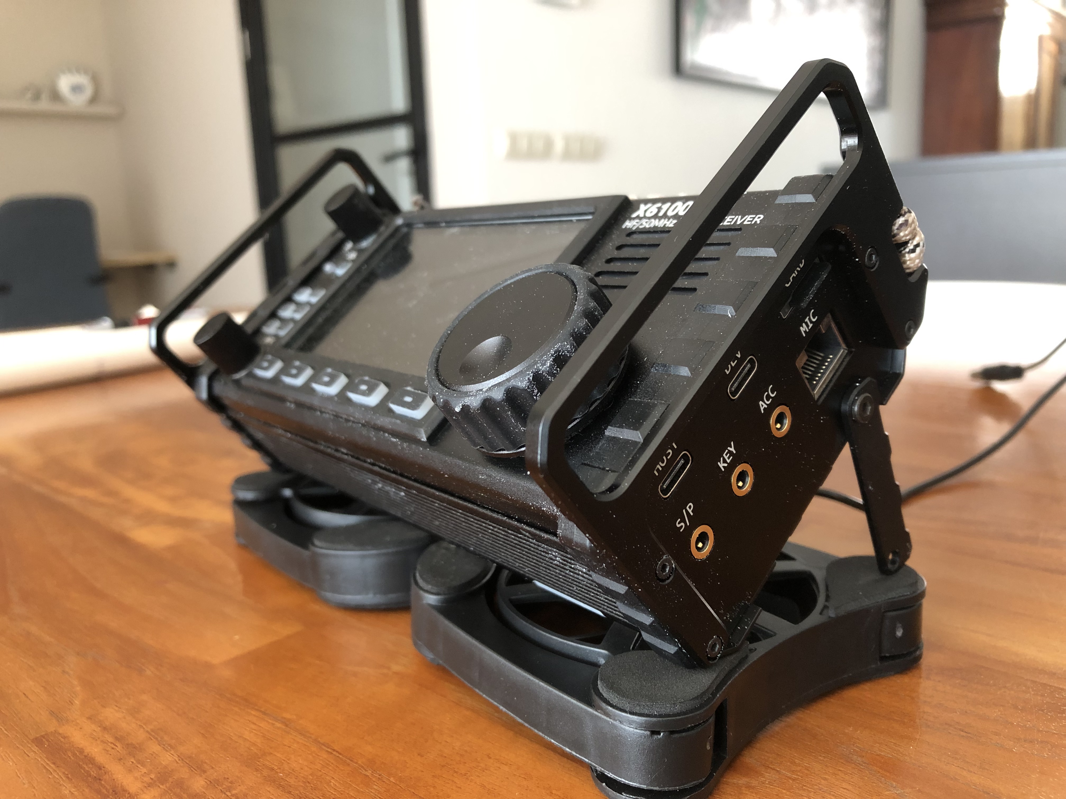
Easy cooling fan for the Xiegu X6100

A while ago I wrote an article on an add on (passive) cooler for the Xiegu X6100. When using this rig intensively, like with some digital modes, my Xiegu X6100 tends to get hot. So firstly, I attached an extra (removable) heatsink. Why a heatsink and not a fan? Well that’s a matter of choice and personal preference. The big advantages of passive cooling are i.m.h.o. that a heatsink this doesn’t need to be powered and the cooling is noiseless. And -last but not least- here is no hassle with cables and connectors, a power supply and the like. It also helped that I had a heatsink in precisely the right size already lying around.

In my original design the heatsink could be removed when not needed. The drawback of my design was that I had to glue magnets on the X6100 to attach the extra heatsink. I can imagine that glueing something to a pristine rig is not the first thing you want. Anyway, I did and it works well.

Fan cooling

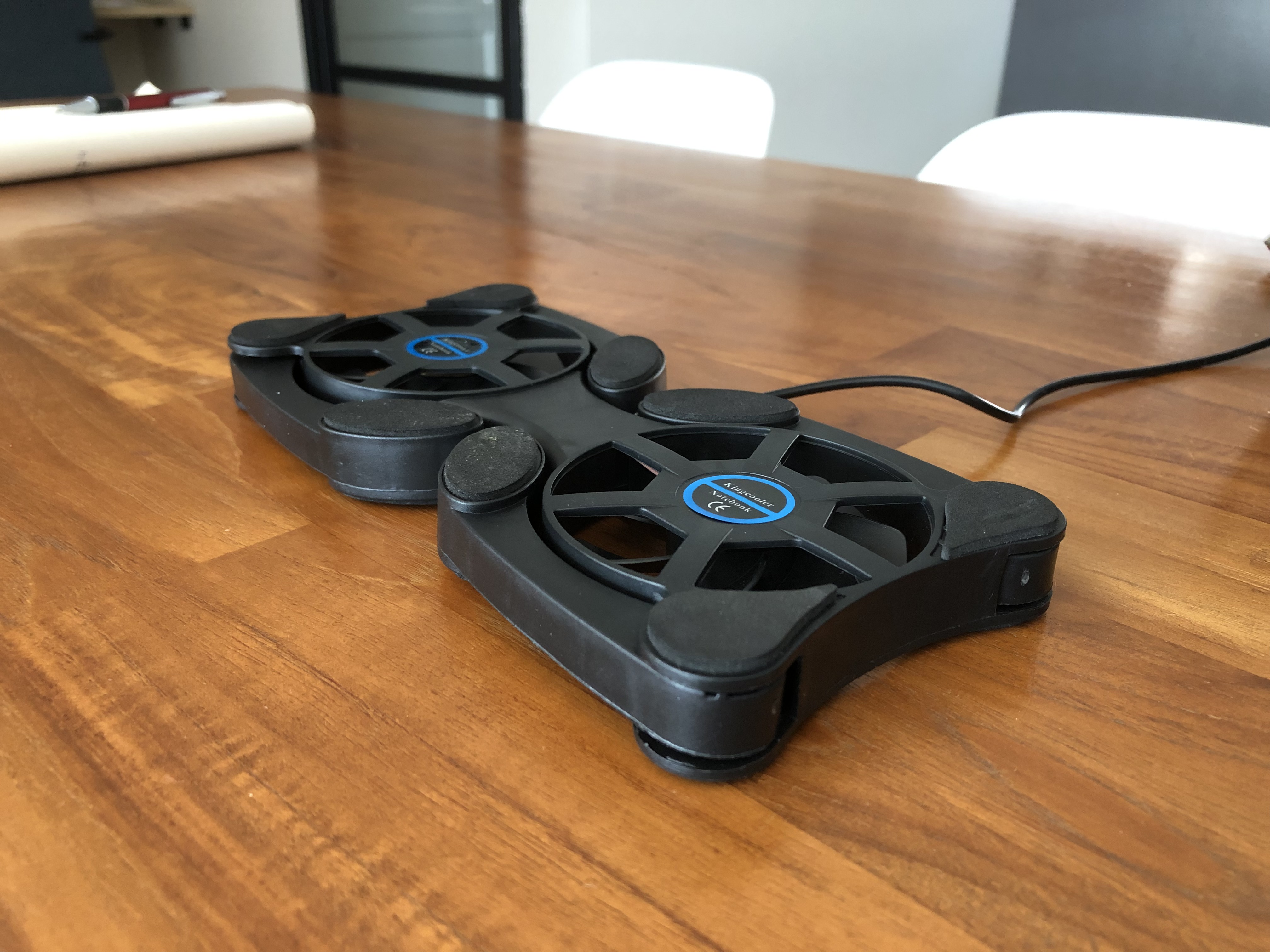
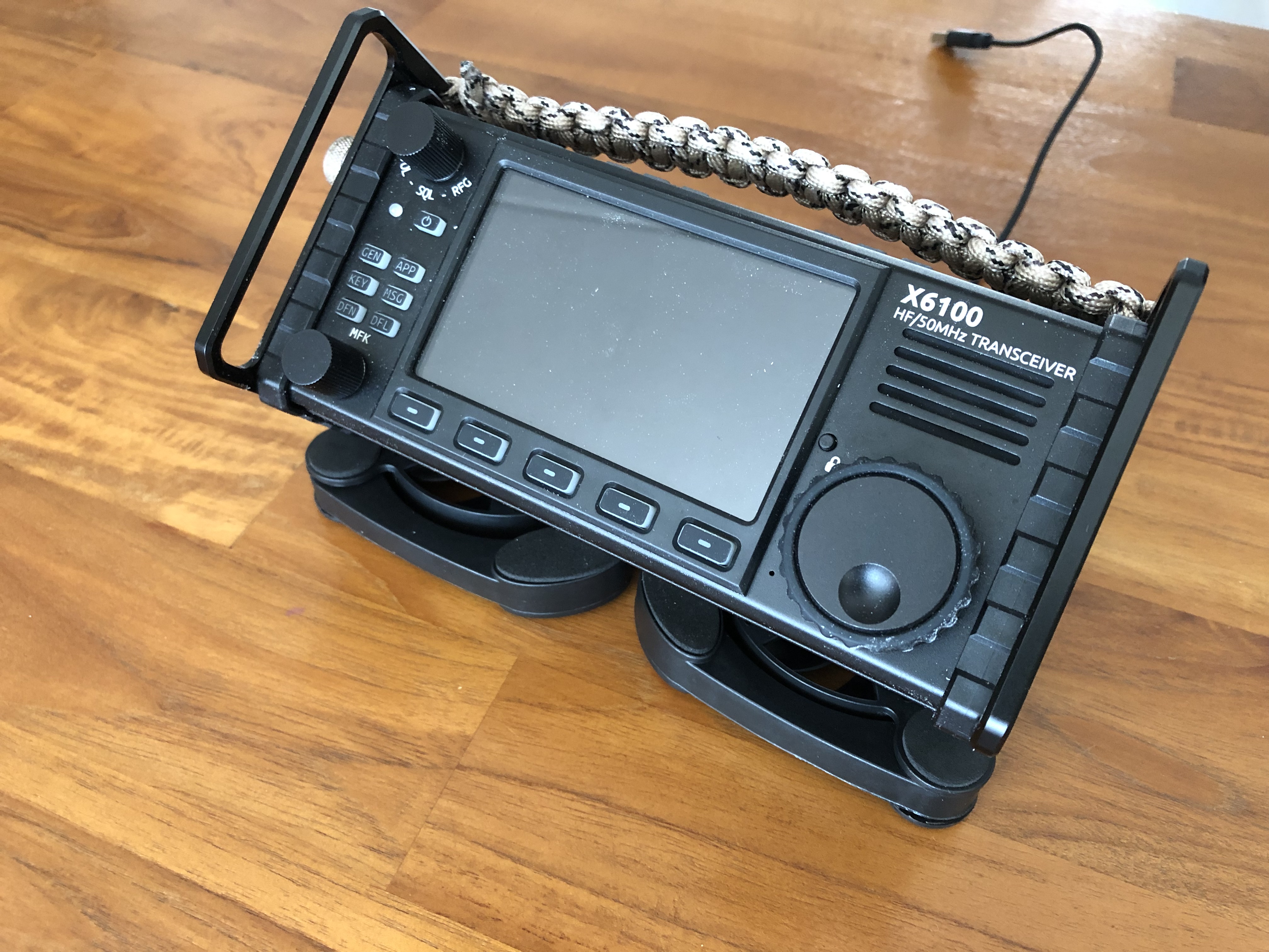
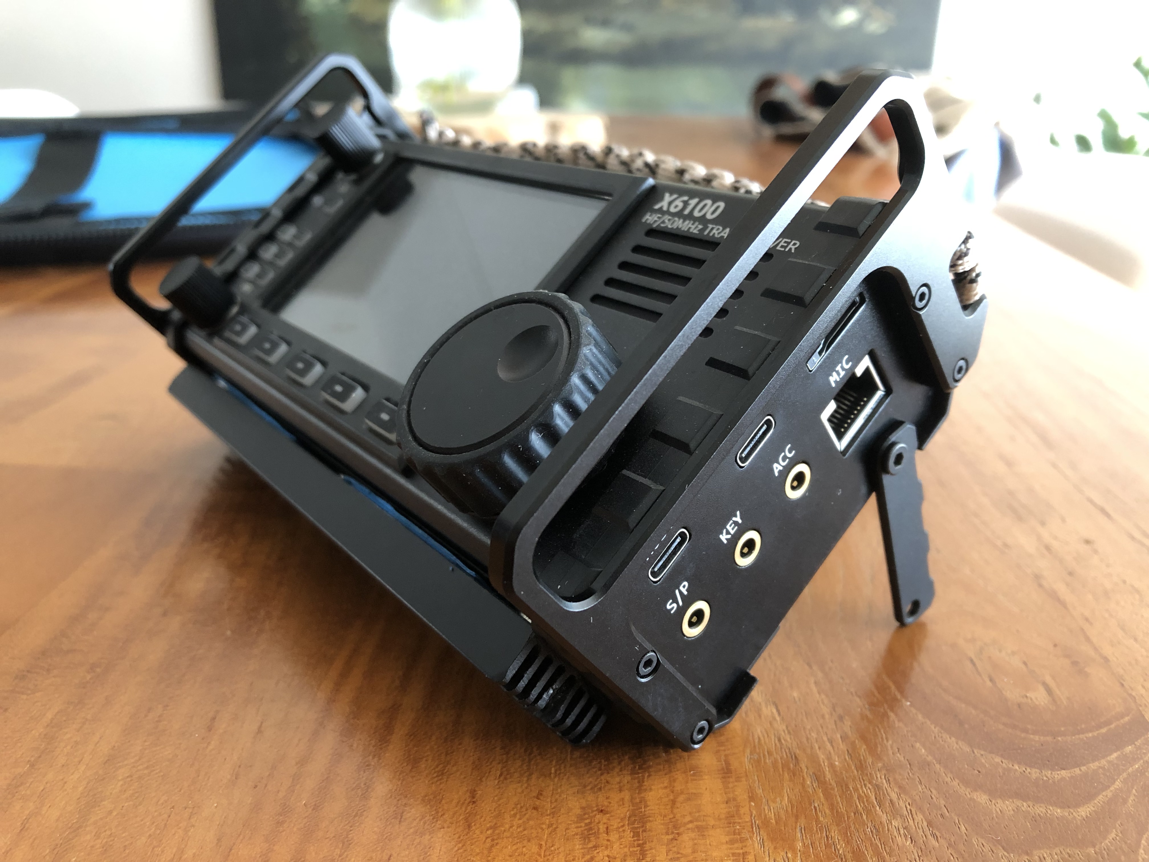
Off course a fan could also do the job. But with a standard (small) fan you also need some kind of contraption to attach it somehow to the radio. Luckily, I recently found a simple solution. It’s not really attached to the rig, but the X6100 can stand on it, in tilted position. A big plus is that this cooler (that consits of two fans) is ready made, has the right size AND is avilable for just a few euro’s on Aliexpress. I’m talking about a USB powered double fan form the brand ‘Kingcooler’, sold as a ‘laptop cooler’. See the picture below:

The use is simple. Normally, for a laptop, you have to unfold it’s legs. But with the legs collapsed (like in the image above) this laptop-cooler has the same size (height x width) as the X6100 itself. As a cooler it fits the X6100 perfectly.

The cooler itself is super quiet. As you might know the best place to cool the Xiegu X6100 is at the bottom. When the Xiegu X6100 / cooler is placed in the position shown in the picture above (and below), the cool air flows towards both the bottom and the back of the rig. This cooler does a good job in keeping my Xiegy X6100 nice and cool.

The cooler weighs just 85 gram and draws 200 mA @ 5V USB (in total).

Tilt stands for the Xiegu G106

I recently purchased Xiegu’s newest radio, the G106. It’s a tiny, sturdy and very basic SDR QRP-HF-transceiver. It’s a bit quirky because it can also be used as a broadcast receiver (HF MW and FM, bands preprogrammed). This makes the rig a great travel companion. The quirkiness also comes back in the design, with rounded corners. I.m.h.o. it’s a beautifull and ergonomically well designed radio. By the way, the design reminds me somewhat of the ELAD FDM DUO.

The Xiegu is basic as in ‘it misses a lot of features that high end radio’s have’. For me that’s not a huge problem, although I miss the opportunity to read the SWR while transmitting.

With an interface it can be connected to a computer. The monochrome LCD is very well readable.

For those of you who watched the very early (and mostly negative) reviews: mine just works fine. I’m happy with the rig.

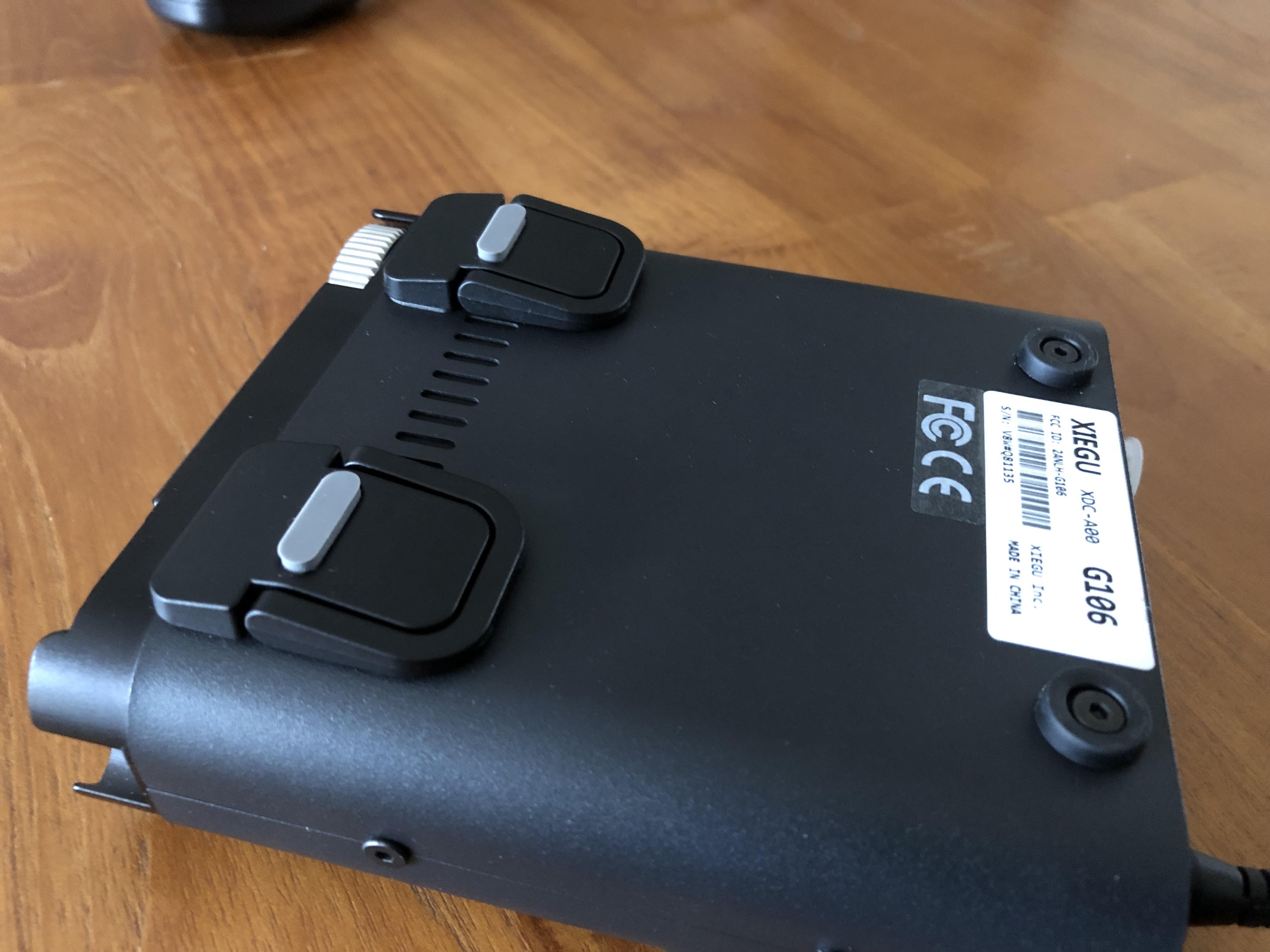
For me the biggest drawback is something very simple: the G106 lacks a tilt stand. As I use the G106 on a table, the lack of a tilt stand is a bit annoying. But also easily solved. I solved the ‘problem’ with after-market tilt stands, sold as ‘laptop stands’ on Ali Express. The ones I bought are self adhevise, made from aluminium and available in black (so they match the G106 ;-).

Attachment is simple: best is to remove the two front feet and replace them by the stands. See the photo’s for the result.

DIY stand for the Xiegu G90

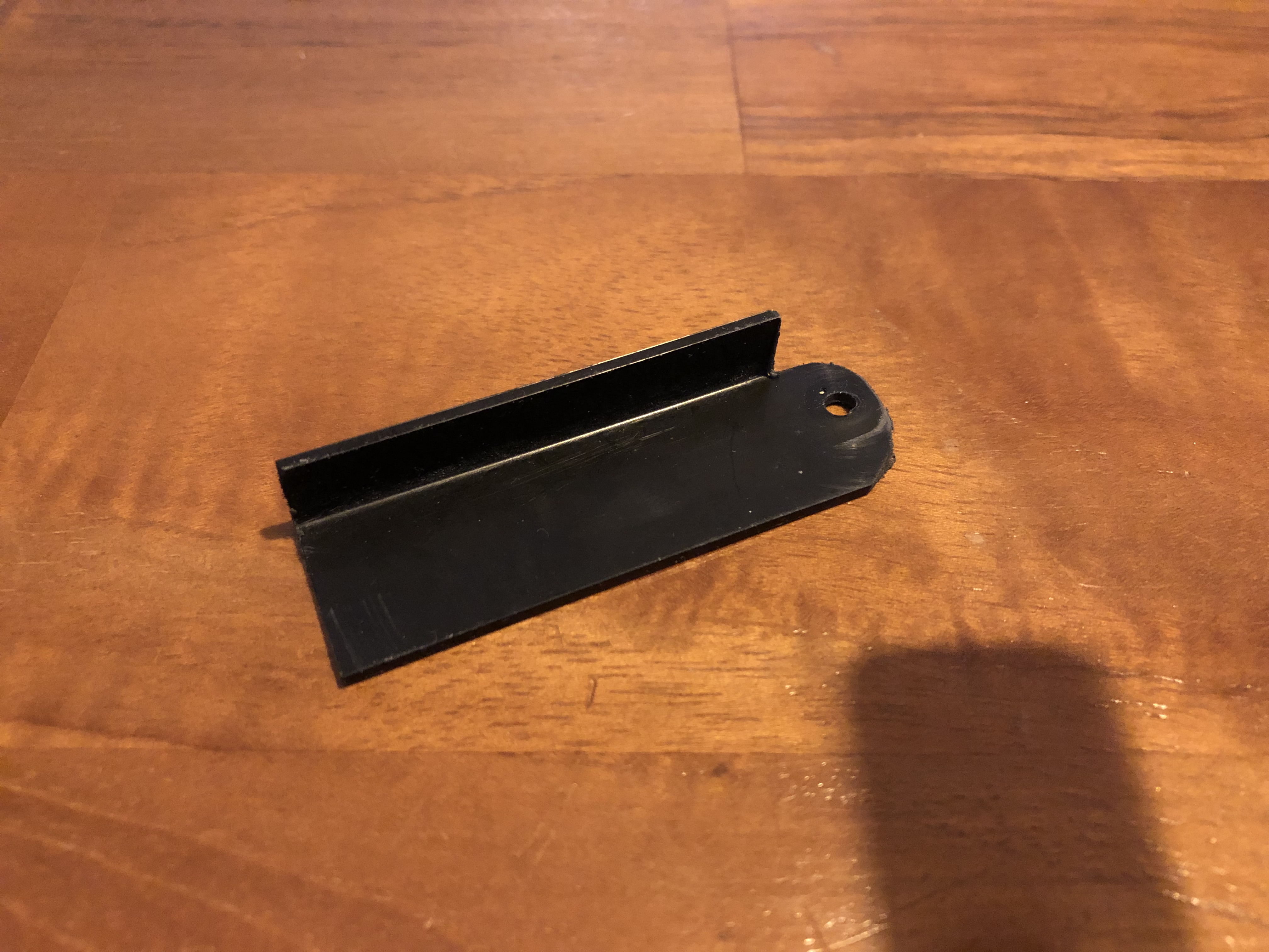
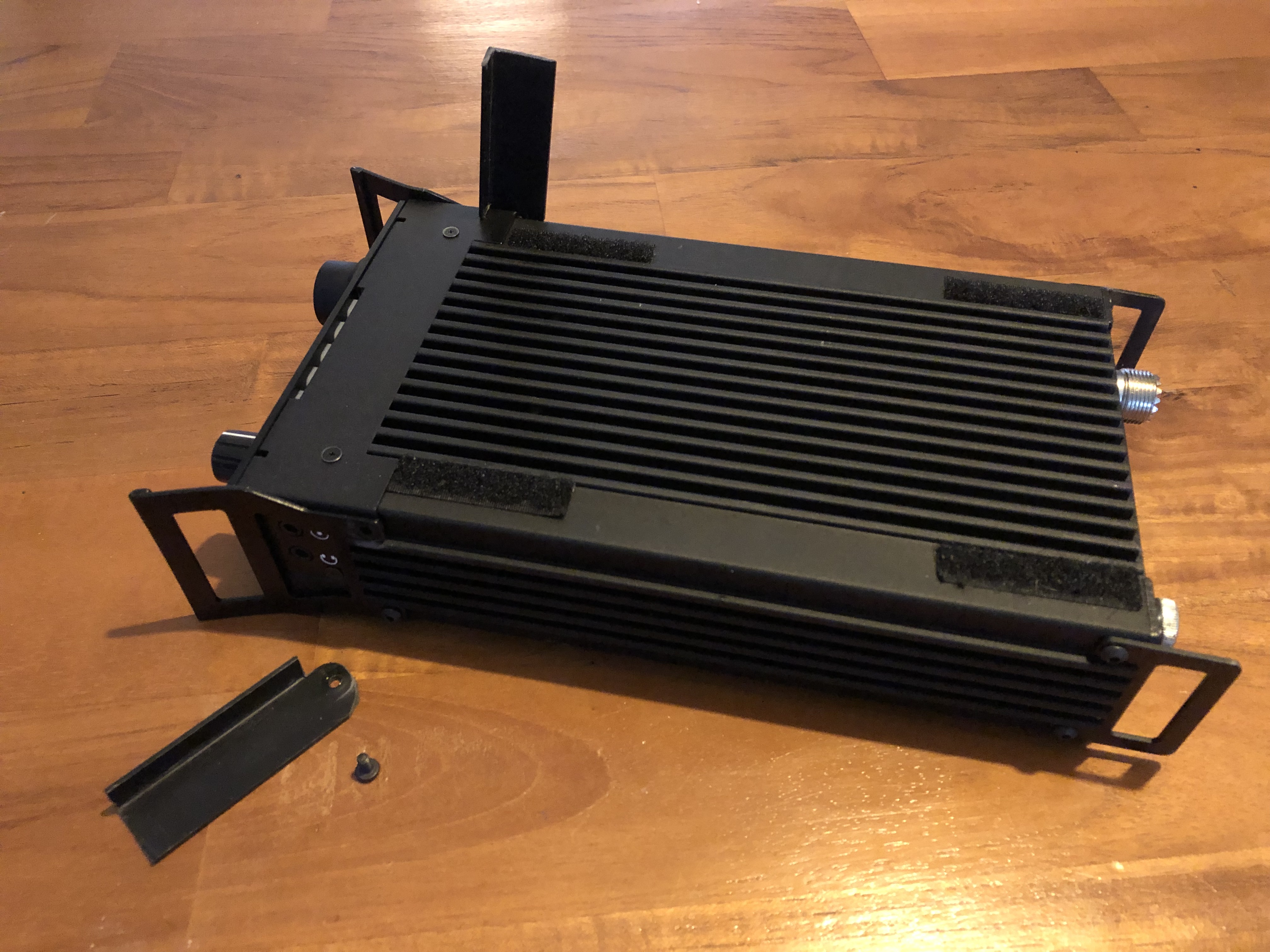
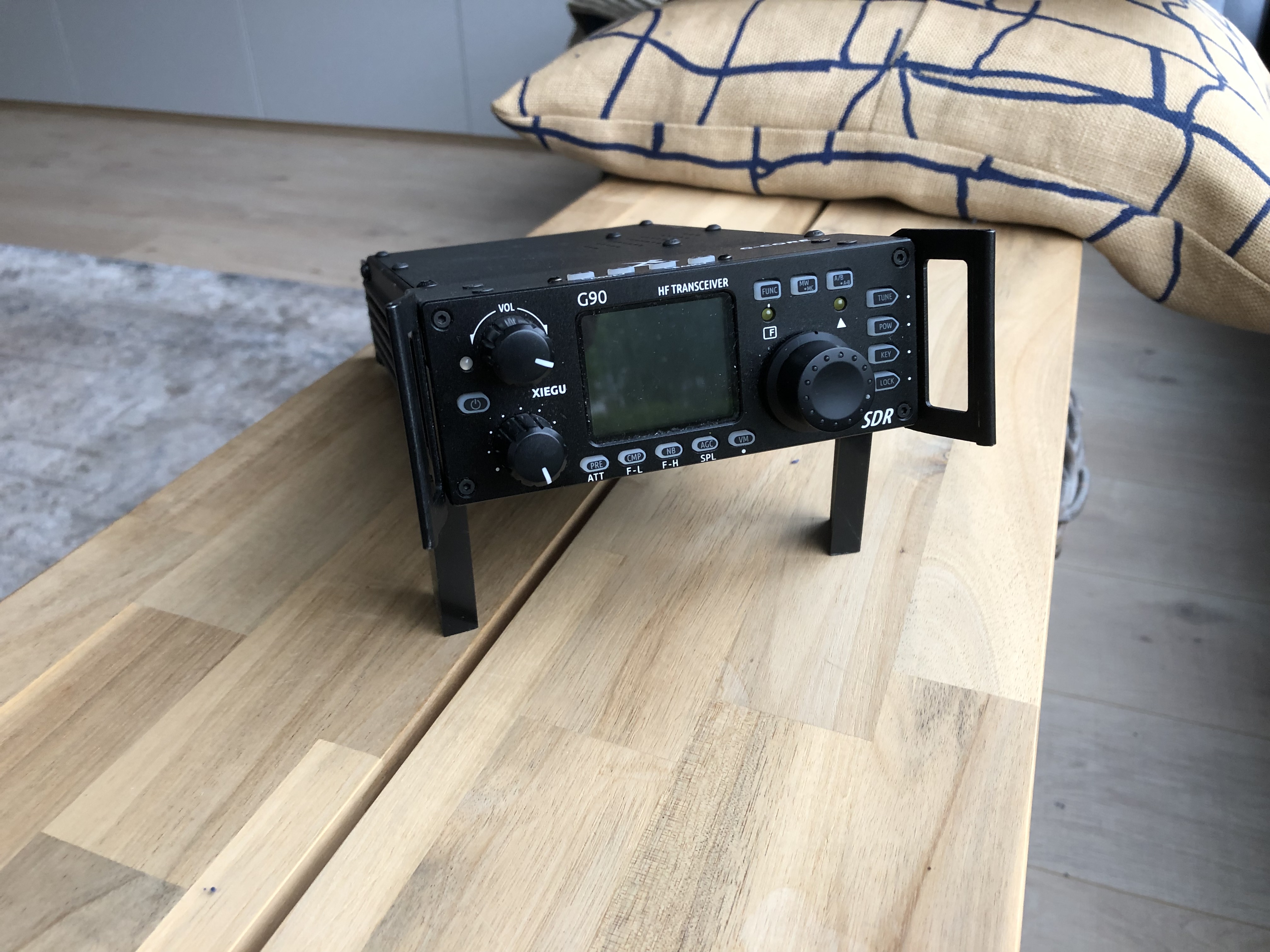
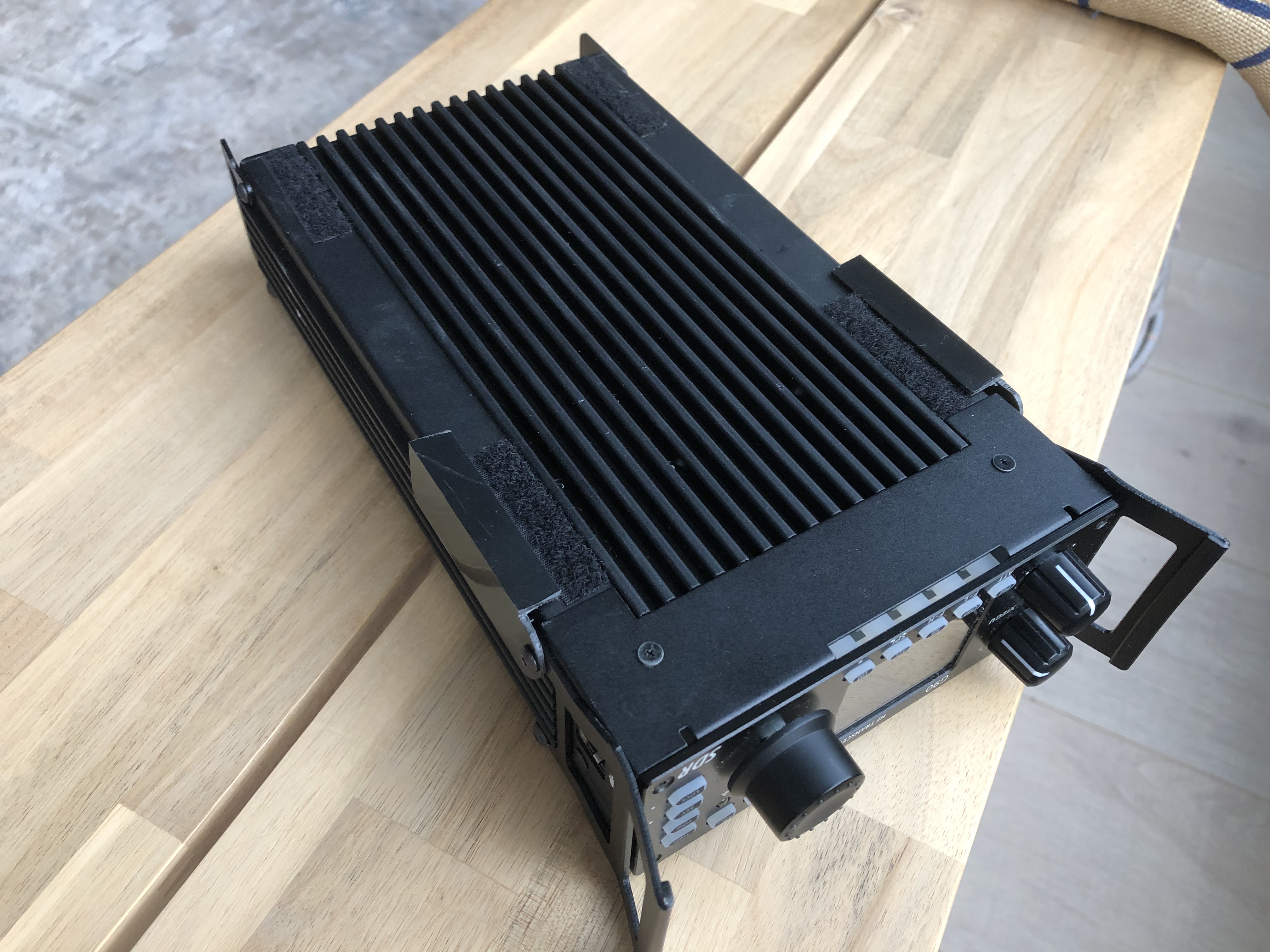
The Xiegu G90 is a manpack style SDR-transceiver, 20 watt and a legendary antenna-tuner. It’s great to use outdoors. But in my opinion the G90 lacks a foldable table stand. I tryed a laptopstand, but found it’s an hassle. I needed something much simpler. So I came with the idea to use two pieces of L-profile and attach them to the front handles of the rig. This would make a simple, lightweight and compact, foldable stand.

It’s easy to make this stand from any plastic (or aluminium) L-profile from a DIY-store. Choose the length of the stands according to your prefered position of the G90 in tilted position. 6 cm worked for me.

By the way: the L-shape of the profile makes the stands more stable than just a flat piece. And: the notch on the top side together with the L-shape secures the position when in use.

Folded back, the stands lay nicely flat to the radio. I used an L-profile of 2 x 1 cm.

You don’t need to drill extra holes in the rig: the stands are attached to the G90 using the holes/bottom screws of the handles.

See the pictures below, they are self explanatory! In my case I choose 6 cm lenght for each stand (in total), the L-profile I used is 2 by 1 cm.

G90 leg (legs are mirrored!)
attach using the bottom screw of the handle
fold up position
fold down position

And does it work? Yes πŸ˜‰

Add-on heatsink for the Xiegu X6100

The Xiegu X6100 is a great radio, but gets hot to the touch when used with digital modes. Mine got as hot as 55 degrees Celsius (130 F). Maybe within specs, but for me too much. The root cause is the transceiver’s heatsink. (and off course the heat production inside). The heatsink has an ‘capital I’-profile, with the largest area of the heatsink inside the radio itself! This is where the heat producing components are mounted. The heat tis then transfed to the outside of the X6100. Only the top and bottom of heatsink of the radio are on the outside: this is the only place where the heat is actually dissipated. Or: … should be dissipated. The problem is that these top and bottom heat dissipating surfaces are not very large and have almost no fins. Result: the rig heats up to an unpleasantly high level.

An alternative way to overcome the X6100 heating problem is by adding a fan. Best place i.m.h.o. at the bottom. But a fan consumes power and produces noise.

Another (more elegant?) way is enlarging the effective dissipation surface where it matters most: at the bottom. Preferably easy removable. The heatsink has to be fixed in a reliable way, preferably without drilling holes in the rig itself. By the way: also the back of the Xiegu dissipates some heat and the surface is relative big. However, the back it is not a part of the actual heatsink and just sheetmetal that happens to touch the heatsink where it is screwed on. Only cooling the back of the rig is not a good idea and that is why I did not put a heatsink to the back. But you could if you want, just keep in mind that it will not be as effective.

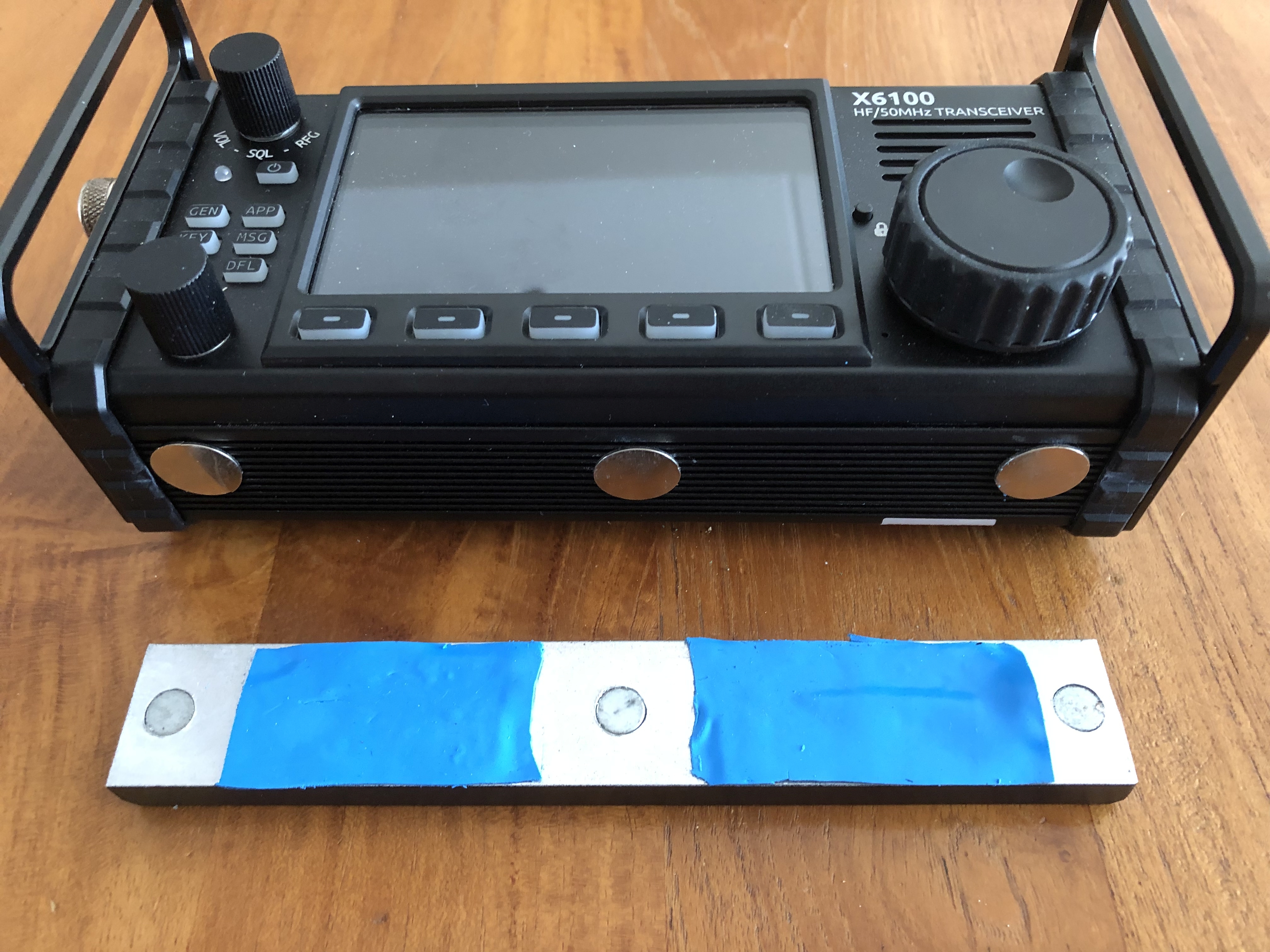
You can see how I attached the add on heatsink without drilling holes. I used magnets -which I glued on the bottom of the rig- and other magnets in the heatsink. When needed (working digital, that’s when the X6100 heats up most) I can add the auxiliary heatsink easily.

As a prototype I used a standard aluminium heatsink (160 x 25 x 10 mm) I had lying round in my shack. These heatsinks are sold for cooling LEDS. I drilled three 8 mm holes in it and glued 3 strong 8mm diameter Nd magnets flush. Between the magnets I added heat conducting pads (1 mm thickness). I spray-painted the heatsink black on the visible side so it looks niver on a black rig. To the bottom of the X6100 I glued 3, 1mm high same thickness as the heat conducting pads) Nd magnets. This contraption makes the heatsink ‘click’ to the rig nicely and also secures that the heat conducting pads are pressed to the rigs bottom heatsink firmly. This to ensure a goof heat transfer the from the bottom to the add on heatsink. As the add on heatsink has a much larger dissipation surface, its capacity is enlaregd significantly. The rig now stays cool nicely. Because the heatsink itself I used is not very high (just 10 mm) the X6100 can still be used in the tilted position. See the picture below.

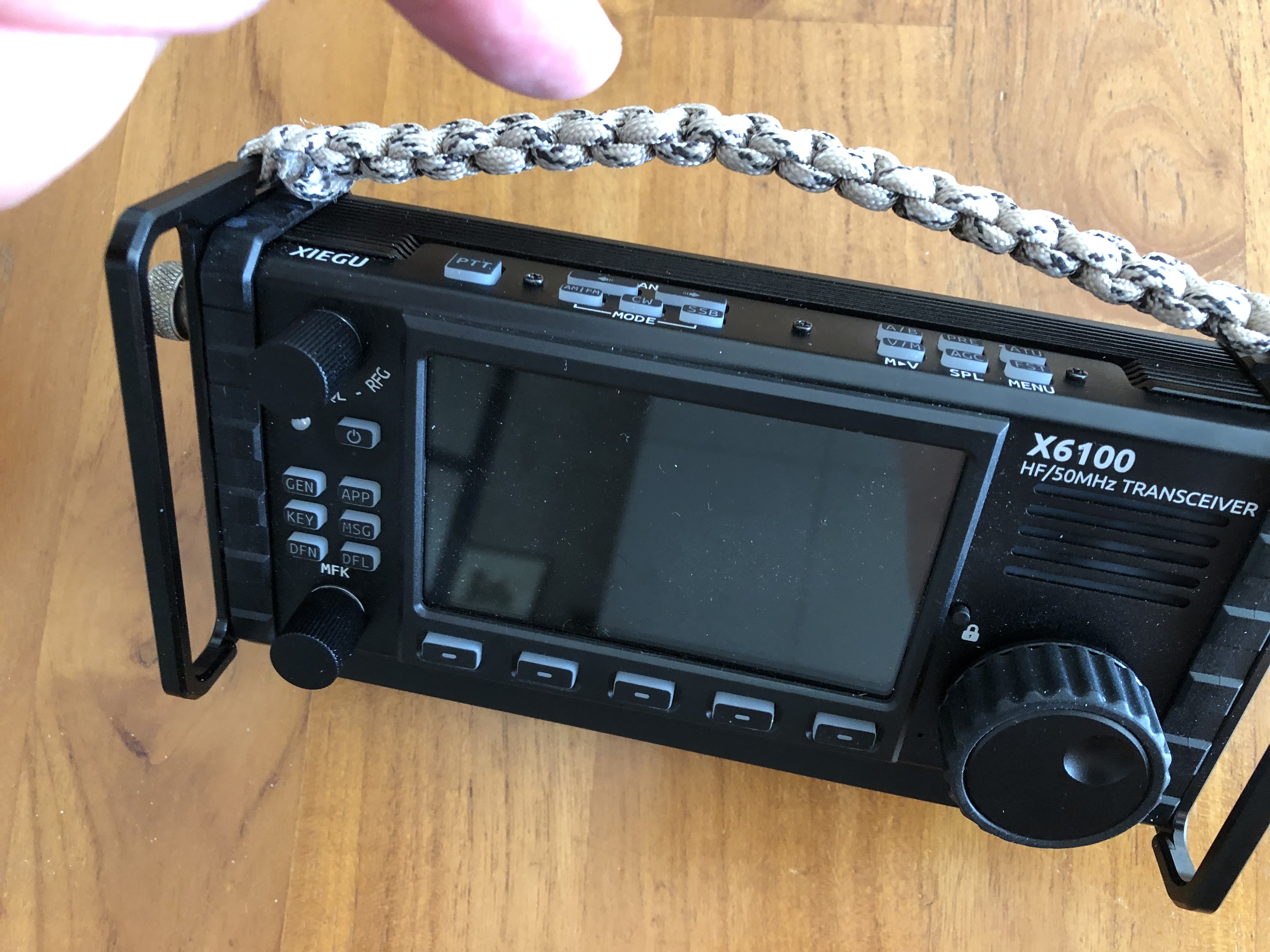
By the way: the heat is -off course- also transported to the top side of the rig and -for a part- to the back. The effective area of the top is even tinier then the bottom because of the buttons. I did not put a heatsink on top, but one could do so. Beware: if your X6100 has the paracord carrying handle you must ensure to keep some space between the handle and the top heatsink. Because when the paracord handle rests on the top-heatsink, it more or less acts like a blanket, hampering the heat dissipation on the top of the rig!

And, does it work? Yes, by adding the heatsink the X6100 stays cool, even when using digital modes. Also: with the heatsink added, the X6100 can still be used in the tilted position.

Why this website is coined Pseudo Voice

Psuedo voice: just an idea for a radical different approach to digital voice over limited channels.

One of the reasons I started this blog and gave this website its name is that I want to share an idea I have for HAM-radio (and other radio communication). Starting point is that on HF ‘voice’ or ‘phone’ needs a relatively large bandwidth compared to many digimodes. Sometimes you just need the excellent SNR-handling and/or narrow bandwidth of digital modes to get the message through. Some digimodes can do this. Voice not.

There are experiments to encode and send coded voice digitally (like freeDV), but that is still a bandwidth-hungry mode compared to -say- PSK31 or even MT63-500

Here my idea of ‘pseudo-voice’ steps in. Psuedo voice is (no surpise!) not real voice, but is in essence it is a series of code-labelled words. That’s why it has the potential to be used in narrow bandwidth channels. They basic idea is you just transmit short codes that represent whole words or even whole sentences. How? First let a computer algorith (AI??) convert speech to ‘words’ and then label each word (or standard sentence) with a unique and (as) short (as possible) code (a so called ‘label’). Then only transmit the sequence of labels. After receiving the labels, they can be converted back to words/sentences (and speech) by using a special look up table: a dictionary. This concept only works if both sides use with the same ‘label dictionary’. that associates the same labels with the same words.

For each type of communication you can develop a seperate tailor-made-dictionary. Like a dictionary for EMCOM, a RAG CHEWING dictionary, et cetera. It’s all about standardisation.

The basic idea behind pseudo voice and its use of dedicated dictionaries is that a meaningfull basic conversation in a normal language only needs a vocabulary of about thousand words (the so called ‘language level A1’). If the conversation is limited to just a few topics (like EMCOM) even less words are needed. Higher laguage levels need more words, complicated grammar and therefore larger dictionaries. By the way: a normal conversational speech speed al level A1 is about 120 words per minute, some of these words form standard sentences that can also have their own label.

Pseudo voice could work ‘like real time’ voice if we use a digimode that does 120 labels per minute. If a label constists of max 5 characters, we would need (netto) max 600 characters per minute = max 10 characters per second. Which small band digimodes can do that? A lot!

More and older/less matured musings:

So: what if each word (and regularly used sentences) has it’s own, short and unique digital ‘label’? And this label is -obviously- shorter than the word itself. You could pair words and labels in a specially written dictonary, that consists of carefully selected words and sentences. Lets say a ‘dictionary HAMQSO’, or a dictionary ‘EMCOM’. Then you could use a speech-to-label engine (STL-e, a variant on the speech-to-text engine) to code speech. And vice versa with a label-to-speech engine (LTSe) . A 120 wpm speech could than be converted to a much lower wpm datastream of ‘labels’.

For use in radio we could -instead of sending real voice- use a STL-engine loaded with a certain dictionary, and send a series of short labels (characters) using a narrow digimode. Say MT63-500 (speed: 5 cps). Labels receveived can be converted back to words (/sentences) and speech using a ‘label to speech’-engine also loaded with this dictionary. Hence ‘pseudo voice’.

NB The sound quality of the pseudo speech is independent from noise in the analog radio channel (as long as the labels are decoded properly): the sound quality depends solely on the quality of sound clips in the LTS-engine. It could be anything from low level computervoices to hifi-speech clips. There are many possibilities to optimise the system to ones needs. One could even have qso’s between diffent foreign languages as long as the labels refer to the same content-dictionary in your own language. ;-). You could use the voice you like (male/female) on the receiving end.

One could use pseudovoice in circumstances where normal HF voice communication is difficult or even impossible (like in situation with low power, compromise antenna’s, bad snr, bad propagation, QRM, etc) and where dedicated digital modes work still OK.

In short: in essence not that the voice itself is digitized and then transmitted, but the use of a dedicated dictionary that labels words (or whole standard sentences) and transmit corrsponding short codes. And vice versa.

For-pupose-dictionaries (aimed at specialized communications) could be developed; for HAM, Emergency, tactical engagements, etc.

Only sending labels (i.e. maximal shorted codes) would greatly reduce HF bandwidth needed (albeit at the cost of a limited dictionary). It doesn’t produce a real conversation, but it comes close (pseudo πŸ˜‰ ) And it is better than nothing!

That’s why I called this webpage ‘pseudo-voice’.

By the way, I may have coined the idea in this blog, but that doesn’t mean I am building or developing it. I am not an engineer or programmer by any means. So I am not able to bring this idea to life in the real world. But it would be nice to hear from you what you think about this idea and even how to bring it forward in the HAM-community. Please post your comments!

DIY alternative for the Elecraft AX-1

Looking around for an extremely small, extremely portable and fast deployable HF field antenna for my QRP transceivers, I stumbled upon the AX-1 from Elecraft. Basicly its a tuned whip antenna. Nothing special. Many other manufacturers are selling those. But the nice feature of (for instance) the AX-1 is that it can be taken apart to make the package even smaller. Just what I was looking for.

The AX-1 consists of a switchable coil-pack, a telescopic whip and one radial. It is easy to set up. And small when stored. Other pro’s of the AX-1 are that the product is ready-made and well build. The con: it is quite expensive for such a simple device (AX-1, about 150 Euro, and when you add the 40m extension coil: count on an extra 80 Euro). This for ‘just a loaded telescopic whip’ that only works on the 20 meter band (OK, with some retuning also on the 15 and 17 meter bands) and (with the extension-pack) on 40 meters! Besides the price: another serious con for me is that there is no way to attach the radial (just one!) to the antenna itself. Elecraft relies on the ground connection of their rigs for this.

More HAM bands

For my QRP field use I would rather like to have a simple all in one solution: a ‘fit in the pocket when collapsed’ antenne. For multiple bands. Much like the AX-1, but also a bit more versatile. And a tad more efficient (this means more radials)! It also should be useable on more bands without changing /adding coils. My in my design multiple bands (6, 10, 20 and 40 meters) van be used without seperate ‘extension-coils’. Just change the tap on the main coil to select the desired band. This makes the antenna IMHO faster deployable, and for more bands.

More radials

Also my design should have a contraption to attach several radials (instead of one) directly to the antenna. The idea behind more radials is that more (1/4 lambda) radials will improve the (inherently low) efficiency of a shortened whip. And also helps the tuning for each seperate band.

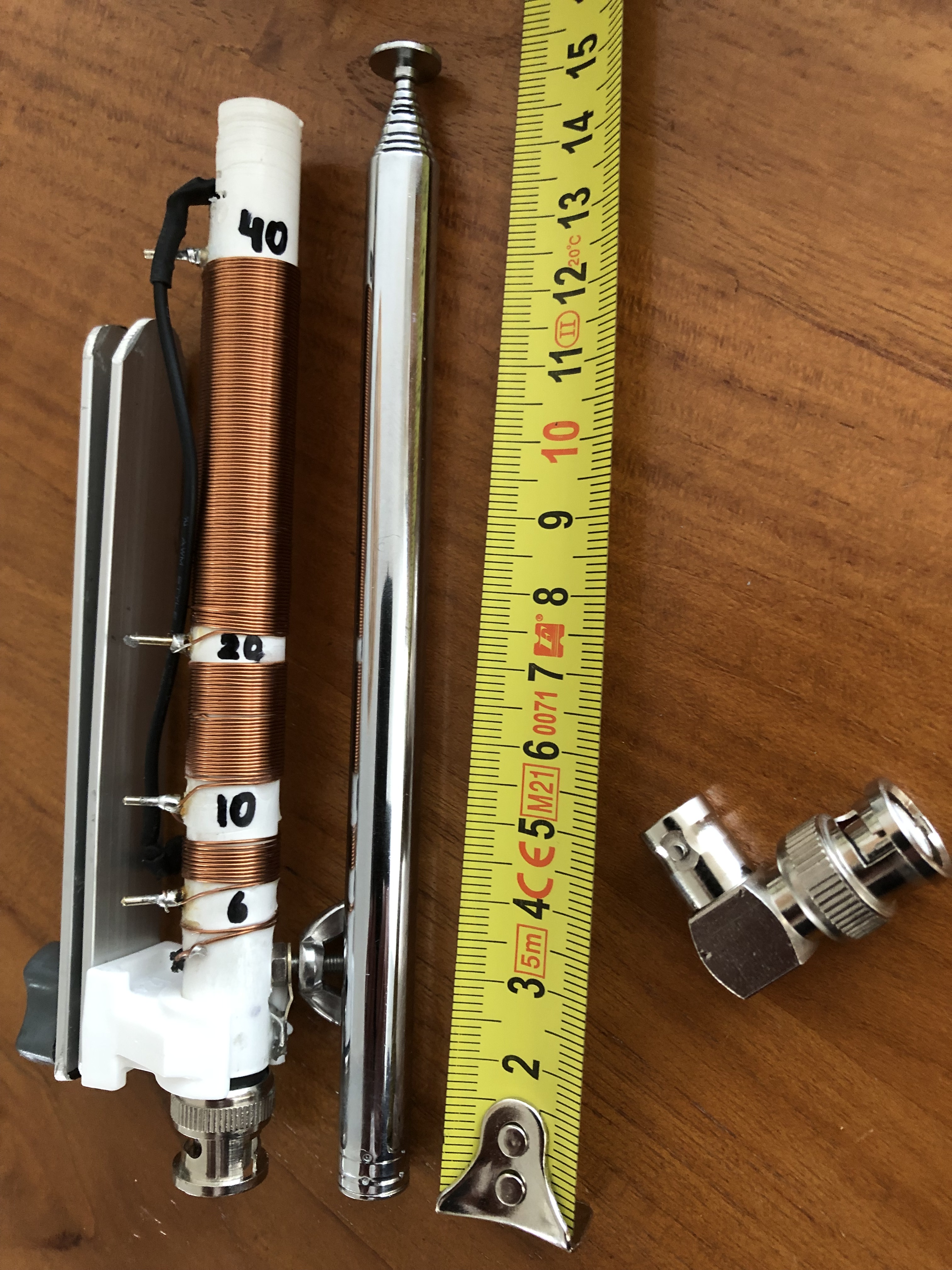
So, with all this in mind, I decided to design and build my own ‘AX-1-ish’-version. I’d need several materials like enemal wire (I used 0,6 m), soldering pins (the one used for PCB’s), a male BNC, etc.

Key for me is the whip. It should be mounted by screwing on the coil assembly to make a reliable (both electrically and mechanically) sound connection. I ordered a seven segment 115 cm long telescopic whip with a M3 threaded hole at it’s base. It was about five euro, shipping included πŸ˜‰

Then I DIY-ed the loading coil(s). As I had to find out the correct number of windings this was preciese and time consuming job. I did not count all the windings (sorry).

With the exception of the 6 meter band: 2 windings ;-).

Guestimating the rest of the windings (by measuring the coil length in cm and dividing by 0,6) you would need:

  • about 10 windings extra for the 10 m segment of the coil;
  • followed by about 28 windings for the 20 m segment, and
  • finally 85 windings for the 40m segment.

If you want to build this antenna yourself: remember the actual inductance depends on the amount of windings, the coil length and the coil diameter.

As you can see in the image below there is no switch in my design. Selecting bands is done by choosing the right tap (shorting out a part of the coil assembly) with the black wire. This black wire is electrically connected to the bottom of the whip (i.e. the top of the coil assembly). The tuning of each part of the coil was done with the help of my trusty nanoVNA.

This is the result:

15 cm when collapsed: super portable!

DIY

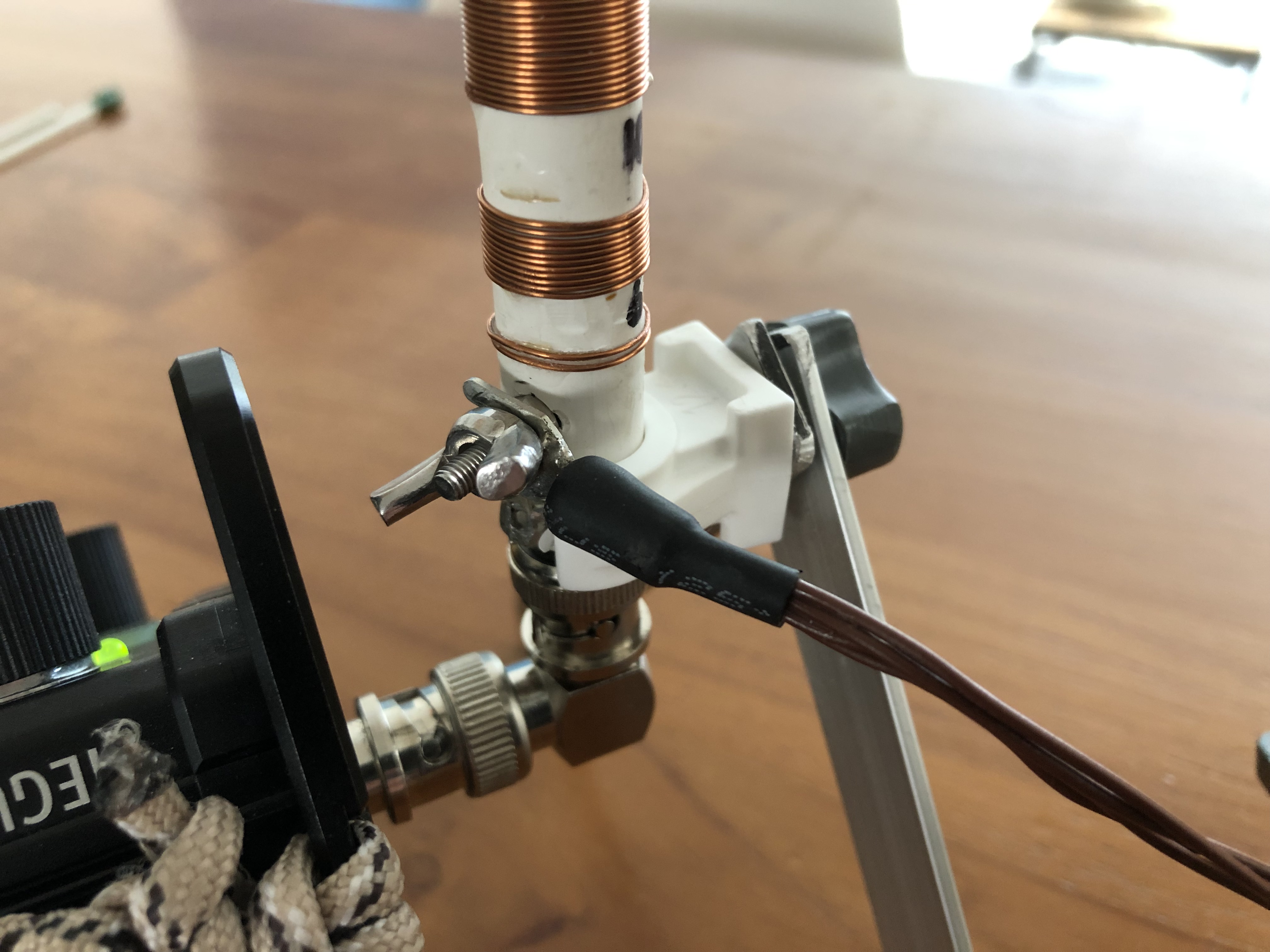
As said above: basically what I did to make the antenna suitable for the desired bands was winding a base loading coil, with taps. Each tap has a terminal. For the terminals I used standard silver coated PCB-pins. The loading coils are wound around a plastic tube, OD 12 mm ID 10 mm. This tube also holds the BNC connector. The BNC’s is core connected to the base (lower end) of the coil assembly. The BNC’s outer part is connected to nut/wing. This acts acts as a ground connector for the radials.

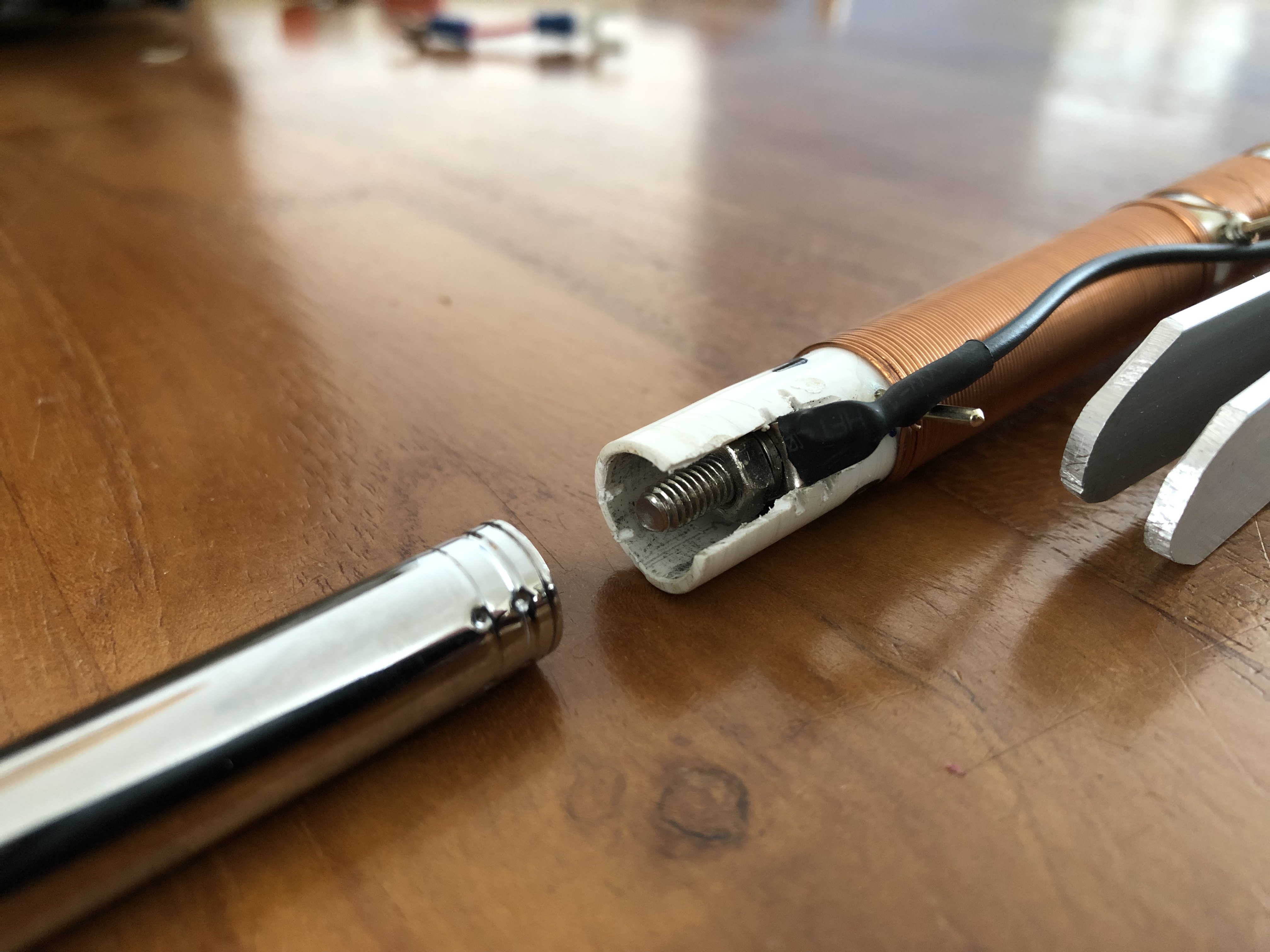
At the top end of the loading coil a M3 bolt is connected. The telescopic whip screws in (it fits snug). The whip connects electrically to the black selection wire.

Band selection is done by selecting the right coil(s) (i.e short out the not desired inductances). In-band tuning is done by adjusting the whip length. No seperate antenna tuner needed!

photo: the telescopic whip is attached to the coil assembly by screwing it on.

Each coil is pre-tuned to the bottom of it’s band (with the whip fully extended). Shortening the whip enables in band tuning: the shorter the whip, the higher the frequency. Off course tuning the coils is only to be done with bot the whip erected AND radials attached!

The radials (one for each band, so a bundle of four radials) are soldered to a spade connector that fits the ground terminal. I also made four non conductive small pins for fixing the radial-ends in the soil if needed.

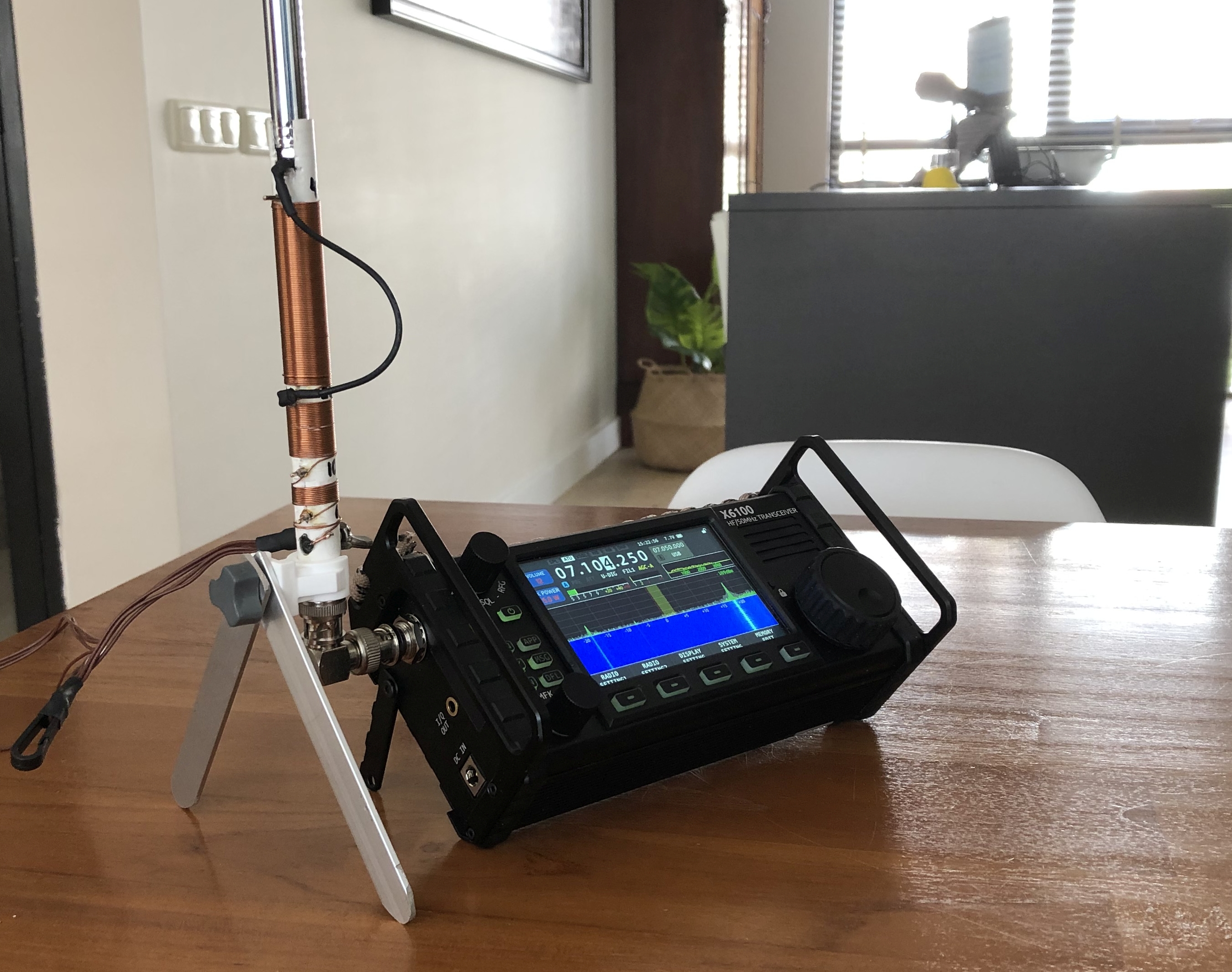
Photo: the bipod made from a plastic tube clamp and two aluminium strips

To attach the antenna directy to my Xiegu X6100 I used an BNC-elbow and an improvised ‘bi-pod’ stand made of a plastic saddle and two aluminium strips. Off course it could be used in any other set up. But this is bipod is practical, light and small.

Does it work? Yes. Absolutely.

But keep in mind that such a short base loaded whip is for sure a compromise antenna! It has a low efficiency compared to a quarter wave vertical. Also keep in mind that I used 0,6 mm enamelled wire for the coil. So this antenna is limited to qrp-use.

Photo: the ground lug for the radials. The lug is connected to the shield of he BNC plug

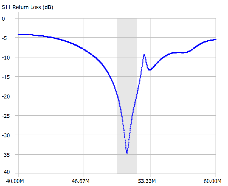
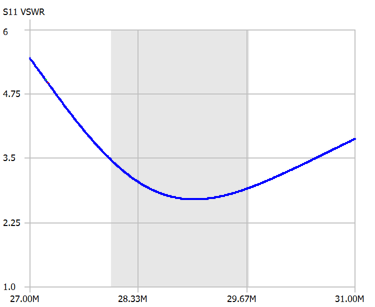
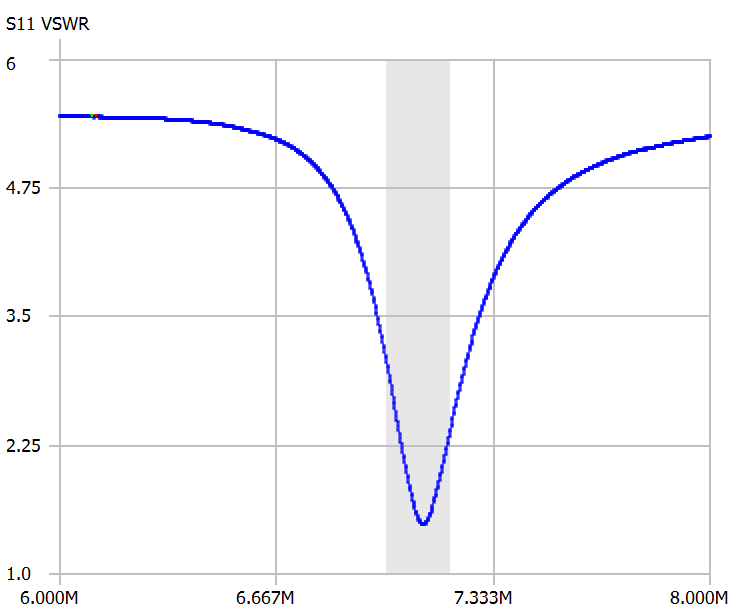
Below see some screenshots from the antenne-analyser for each HAM band.

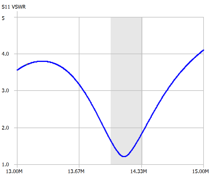
fig 1: antenna when tuned to the centre of the 6m band
fig 3: antenna when tuned to the centre of the 20 m-band