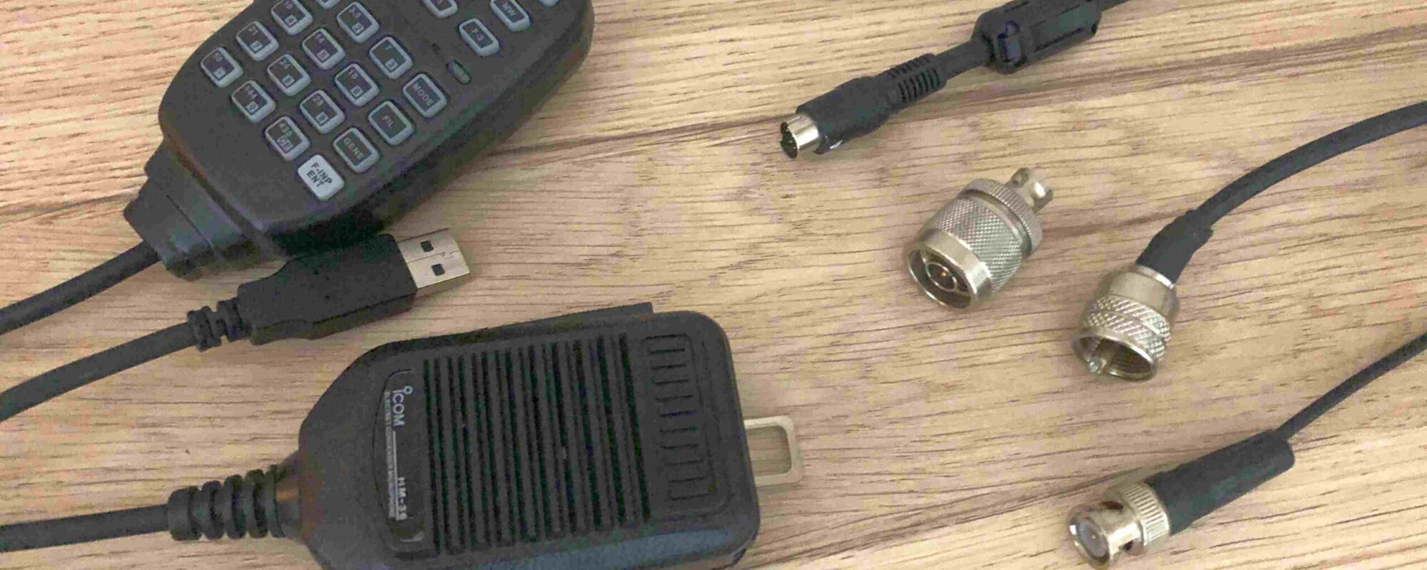
Looking around for an extremely small, extremely portable and fast deployable HF field antenna for my QRP transceivers, I stumbled upon the AX-1 from Elecraft. Basicly its a tuned whip antenna. Nothing special. Many other manufacturers are selling those. But the nice feature of (for instance) the AX-1 is that it can be taken apart to make the package even smaller. Just what I was looking for.
The AX-1 consists of a switchable coil-pack, a telescopic whip and one radial. It is easy to set up. And small when stored. Other pro’s of the AX-1 are that the product is ready-made and well build. The con: it is quite expensive for such a simple device (AX-1, about 150 Euro, and when you add the 40m extension coil: count on an extra 80 Euro). This for ‘just a loaded telescopic whip’ that only works on the 20 meter band (OK, with some retuning also on the 15 and 17 meter bands) and (with the extension-pack) on 40 meters! Besides the price: another serious con for me is that there is no way to attach the radial (just one!) to the antenna itself. Elecraft relies on the ground connection of their rigs for this.
More HAM bands
For my QRP field use I would rather like to have a simple all in one solution: a ‘fit in the pocket when collapsed’ antenne. For multiple bands. Much like the AX-1, but also a bit more versatile. And a tad more efficient (this means more radials)! It also should be useable on more bands without changing /adding coils. My in my design multiple bands (6, 10, 20 and 40 meters) van be used without seperate ‘extension-coils’. Just change the tap on the main coil to select the desired band. This makes the antenna IMHO faster deployable, and for more bands.
More radials
Also my design should have a contraption to attach several radials (instead of one) directly to the antenna. The idea behind more radials is that more (1/4 lambda) radials will improve the (inherently low) efficiency of a shortened whip. And also helps the tuning for each seperate band.
So, with all this in mind, I decided to design and build my own ‘AX-1-ish’-version. I’d need several materials like enemal wire (I used 0,6 m), soldering pins (the one used for PCB’s), a male BNC, etc.
Key for me is the whip. It should be mounted by screwing on the coil assembly to make a reliable (both electrically and mechanically) sound connection. I ordered a seven segment 115 cm long telescopic whip with a M3 threaded hole at it’s base. It was about five euro, shipping included 😉
Then I DIY-ed the loading coil(s). As I had to find out the correct number of windings this was preciese and time consuming job. I did not count all the windings (sorry).
With the exception of the 6 meter band: 2 windings ;-).
Guestimating the rest of the windings (by measuring the coil length in cm and dividing by 0,6) you would need:
- about 10 windings extra for the 10 m segment of the coil;
- followed by about 28 windings for the 20 m segment, and
- finally 85 windings for the 40m segment.
If you want to build this antenna yourself: remember the actual inductance depends on the amount of windings, the coil length and the coil diameter.
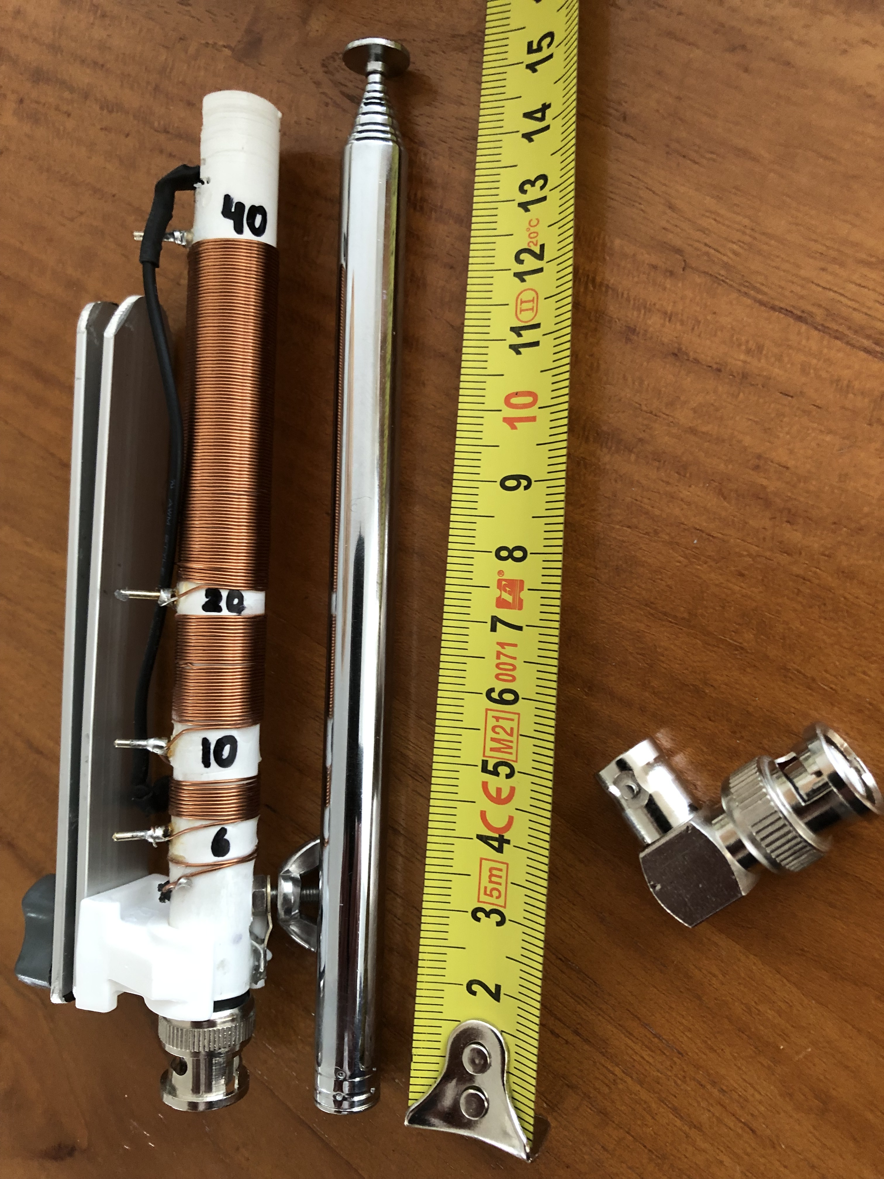
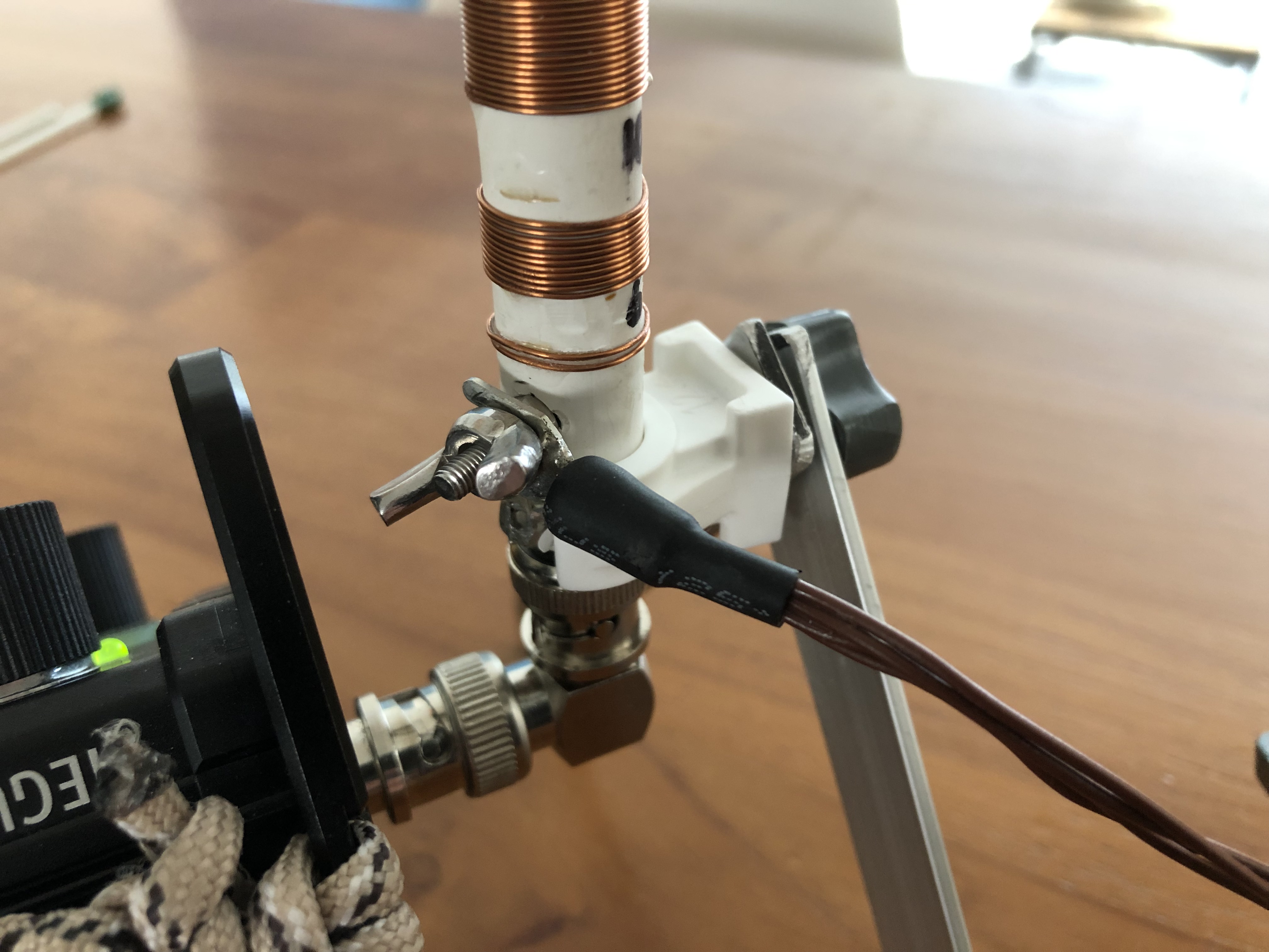
As you can see in the image below there is no switch in my design. Selecting bands is done by choosing the right tap (shorting out a part of the coil assembly) with the black wire. This black wire is electrically connected to the bottom of the whip (i.e. the top of the coil assembly). The tuning of each part of the coil was done with the help of my trusty nanoVNA.
This is the result:
DIY
As said above: basically what I did to make the antenna suitable for the desired bands was winding a base loading coil, with taps. Each tap has a terminal. For the terminals I used standard silver coated PCB-pins. The loading coils are wound around a plastic tube, OD 12 mm ID 10 mm. This tube also holds the BNC connector. The BNC’s is core connected to the base (lower end) of the coil assembly. The BNC’s outer part is connected to nut/wing. This acts acts as a ground connector for the radials.
At the top end of the loading coil a M3 bolt is connected. The telescopic whip screws in (it fits snug). The whip connects electrically to the black selection wire.
Band selection is done by selecting the right coil(s) (i.e short out the not desired inductances). In-band tuning is done by adjusting the whip length. No seperate antenna tuner needed!
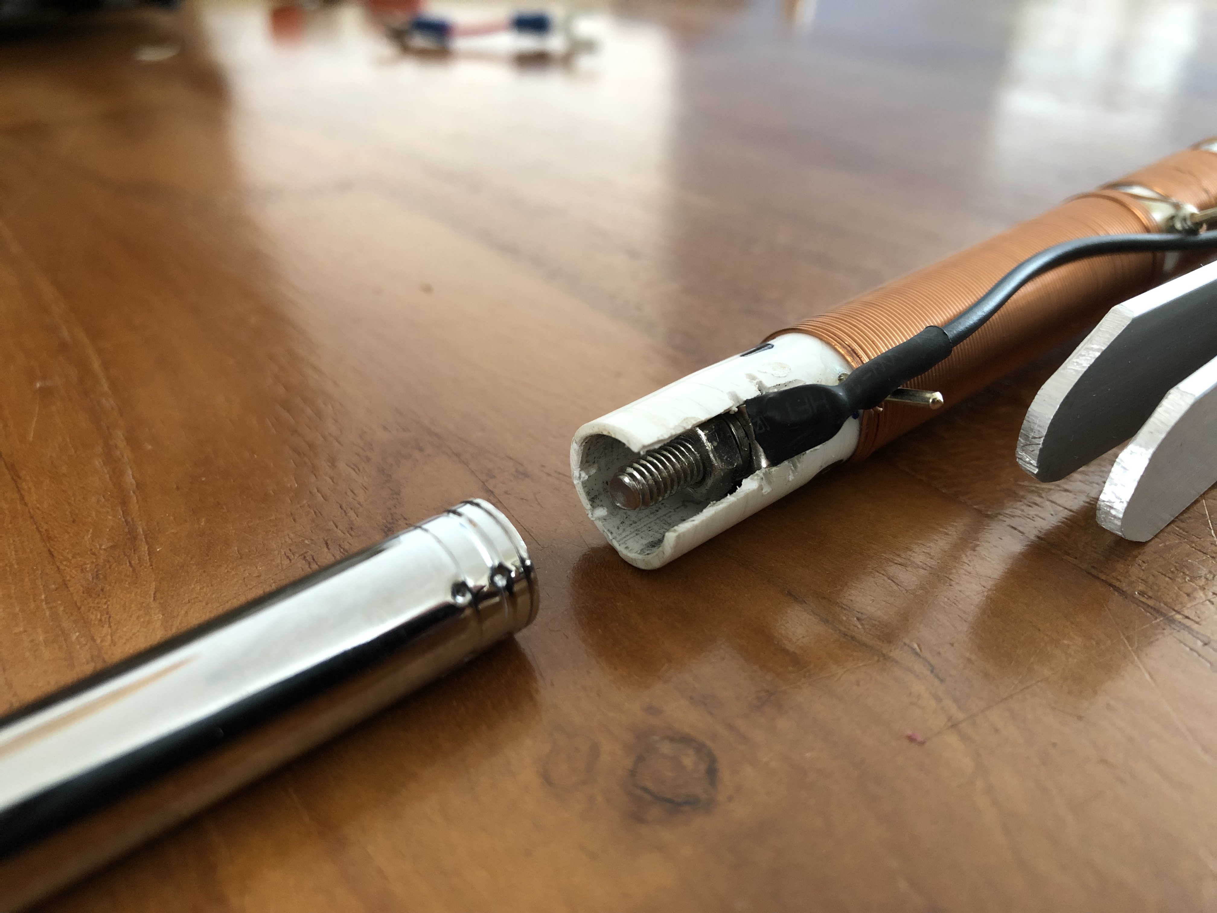
Each coil is pre-tuned to the bottom of it’s band (with the whip fully extended). Shortening the whip enables in band tuning: the shorter the whip, the higher the frequency. Off course tuning the coils is only to be done with bot the whip erected AND radials attached!
The radials (one for each band, so a bundle of four radials) are soldered to a spade connector that fits the ground terminal. I also made four non conductive small pins for fixing the radial-ends in the soil if needed.
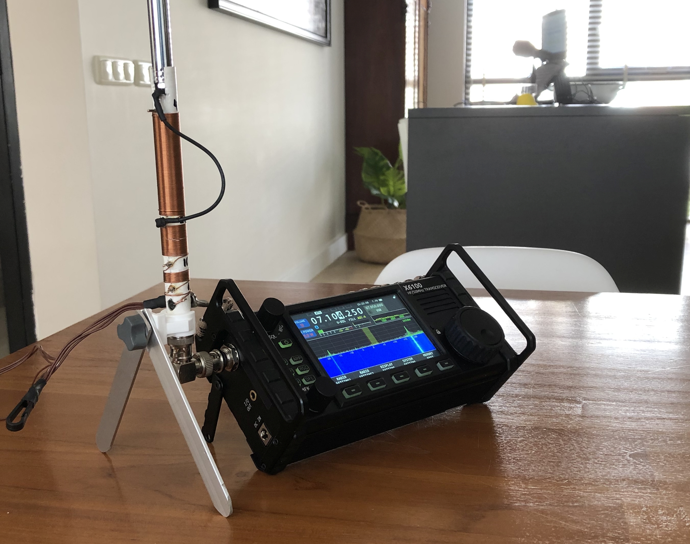
To attach the antenna directy to my Xiegu X6100 I used an BNC-elbow and an improvised ‘bi-pod’ stand made of a plastic saddle and two aluminium strips. Off course it could be used in any other set up. But this is bipod is practical, light and small.
Does it work? Yes. Absolutely.
But keep in mind that such a short base loaded whip is for sure a compromise antenna! It has a low efficiency compared to a quarter wave vertical. Also keep in mind that I used 0,6 mm enamelled wire for the coil. So this antenna is limited to qrp-use.
Below see some screenshots from the antenne-analyser for each HAM band.
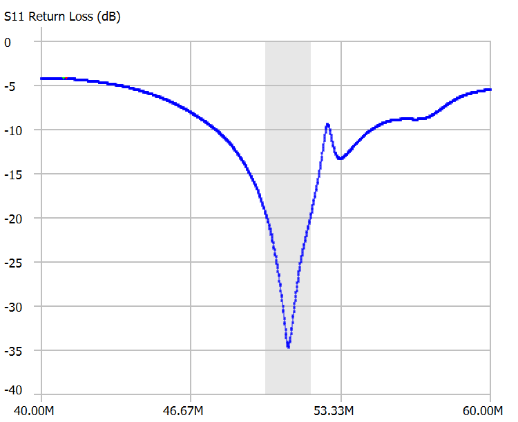
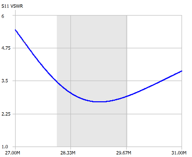
fig 2: antenna when tuned to the centre of the 10m band
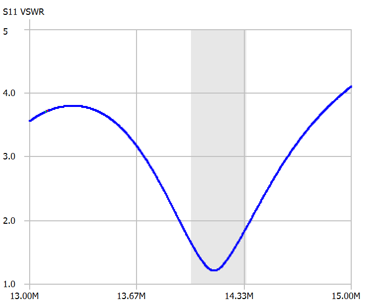
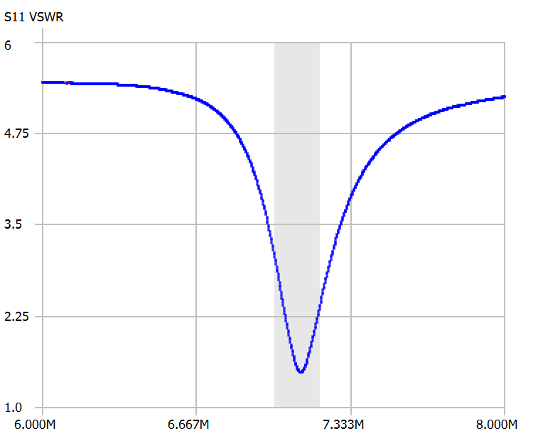
Fig 4: antenna when tuned to the centre of the 40 m band
